The electric valve positioner is the main accessory of the pneumatic control valve, and is usually used in conjunction with the pneumatic control valve. It converts the electrical signal in the control room into a gas signal, and then controls the opening of the regulating valve. According to different debugging methods, positioners are divided into mechanical electric positioners and intelligent electric positioners.
Mechanical electrical positioner
1) Principle
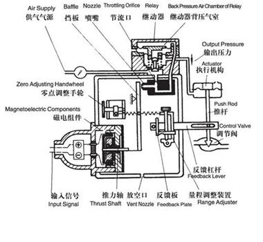
When current is input into the coil, the iron core is magnetized. Under the action of the magnetic field, the iron core drives the baffle close to the nozzle, the air pressure in the back pressure chamber of the relay increases, and the output pressure increases, pushing the valve stem upward, and the feedback lever swings counterclockwise. The spring tension on the range adjustment device is reduced, and the distance between the baffle and the nozzle is gradually increased, until the balance is reached, and the valve is stabilized at a certain opening. The electromagnetic force generated by the coil input current is different, and then the different opening of the valve is controlled.

Schematic diagram of mechanical electrical positioner
2) Advantages and disadvantages
This type of positioner has a simple structure, is not easy to be damaged, and does not require high compressed air quality.
However, the debugging efficiency of the mechanical positioner is low, and the zero point and stroke need to be adjusted back and forth; as the ambient temperature changes, the spring force changes, and the valve opening is prone to offset; the tightness of the screws that fix the spring and the baffle will increase the relative moving parts Friction affects the accuracy of the positioner, especially when there is vibration, the screws are easy to loosen, and the opening and accuracy will change after a period of use.
3) How to use it correctly
The connection of the mechanical positioner and the actuator is related to the functioning mode of the actuator. The air outlet of the positioner and the position of the "range adjustment device" should be correctly selected in accordance with the requirements of the positioner's instruction manual.
During the commissioning process, all screws should be loosened as much as possible to prevent affecting the adjustment accuracy; adjust the input signal to 4.3mA, and then turn the "zero point adjustment handwheel" until the valve stem has a slight movement; then the input signal is changed to 20mA, and turn The handwheel of the "range adjustment device" until the valve stroke meets the design requirements; at this time, the valve zero point will change, repeat the above operations until the valve zero point and stroke meet the requirements.